
What Every Transmission Engineer Should Know About Choosing Cable Bonding Schemes
Every high-voltage (HV) and extra-high-voltage (EHV) single-core power cable relies on its metallic sheath system such as a copper wire screen and a metallic moisture barrier, for two essential functions: electrostatic shielding and providing a low-impedance return path for earth fault currents. Yet the way you bond and ground that metallic sheath along a cable route determines whether the circuit delivers its full rated ampacity or suffers from severe thermal derating and hazardous standing voltages.
To understand why sheath bonding is one of the most consequential levers in underground transmission design, trace the electromagnetic cause-and-effect chain inside an energized single-core cable:
1. Induced Voltage (The Root Cause): Alternating current in the phase conductor creates a time-varying magnetic field around the cable. By Faraday's Law, this changing magnetic flux induces an electromotive force (EMF) along the metallic sheath. This induced voltage is present in all cable installations, irrespective of the bonding method, even when the sheath is not part of a closed current path.
2. Circulating Current (λ₁′): Whenever the metallic sheath forms a closed loop (such as in both-ends solid bonding), that induced EMF drives a continuous circulating current between bonding points. This current generates I²R heating losses in the sheath that directly reduce cable ampacity.
3. Eddy Current (λ₁″): Even when the sheath loop is broken, the time-varying magnetic field drives localized swirling eddy currents within the sheath wall itself. While much smaller than circulating currents, eddy currents appear in all bonding schemes and increase with load current, sheath thickness, supply frequency, and magnetic coupling from adjacent circuits.
4. Total Sheath Loss Factor (λ₁): Circulating and eddy contributions combine into a single Sheath Loss Factor (λ₁ = λ₁′ + λ₁″), where total sheath loss is expressed as a fraction of conductor loss (Ws = λ₁ × Wc). For example, λ₁ = 0.2 means the metallic sheath dissipates an extra 20% of the conductor's I²R loss as heat.
1. Sheath Bonding Must Simultaneously Limit Circulating Currents and Clamp Standing Voltages
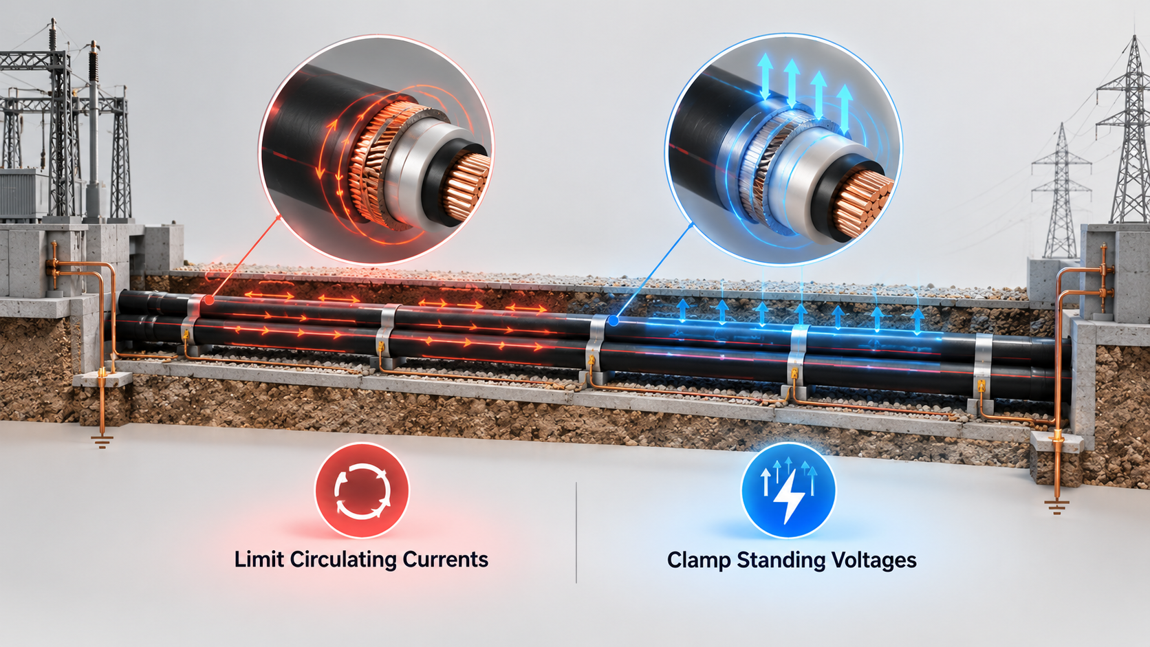
· Selecting a bonding scheme is an exercise in balancing four competing engineering objectives: reducing sheath losses (λ₁), limiting induced sheath voltage, improving cable transmission efficiency, and ensuring personnel and cable system safety under normal and fault conditions.
· Utility and international standards including SEC-ES-1104-08, IEC 60287-1-1:2023, and IEEE Std 575-2014 establish strict quantitative boundaries for both sheath circulating currents and induced sheath voltages:
· Circulating Current Limits (SEC-ES-1104-08, Clauses 2.5.6 & 2.5.7):
· Sheath circulating current must not exceed 5% of the cable conductor current for duct bank installations, or 3% of the cable conductor current for direct-buried installations. Designers must also account for mutual proximity effects from neighboring energized circuits, which can induce circulating currents even on a circuit that is not yet energized.
·
· Standing & Fault Induced Voltage Limits (SEC-ES-1104-08, Clauses 2.11.1a & 2.11.1b): When a cable sheath is isolated from earth to eliminate circulating currents, standing voltage accumulates along the open section length. The induced voltage must remain within the applicable safety limits.
|
Rated System Voltage |
Max Induced Voltage (Normal) |
Max Induced Voltage (Fault) |
Standard Reference |
|
110, 115 & 132 kV (HV) |
200 V |
5,000 V |
SEC-ES-1104-08, R0 (Clauses 2.11.1a & b) |
|
230 & 380 kV (EHV) |
200 V |
10,000 V |
SEC-ES-1104-08, R0 (Clauses 2.11.1a & b) |
2. Route Length and Fault Return Paths Dictate Which of the Four Bonding Families Fits Your Circuit
All practical HV and EHV sheath bonding arrangements fall into four primary families, each suited to specific route lengths and grounding topologies:
Family 1: Solid Bonding (Both-Ends and Multi-Point Bonding)
In a solid bonding arrangement, the metallic sheath is solidly earthed at both terminations (and occasionally at intermediate points). It offers the simplest installation with no link boxes, no Sheath Voltage Limiters (SVLs), and no separate Earth Continuity Conductor (ECC / Parallel Ground Continuity Cable, GCC), while clamping termination voltages to zero. However, because the closed loop allows continuous circulating current (λ₁ can approach 1.0), solid bonding severely derates cable ampacity and is restricted to short runs or low-current applications.
Family 2: Single-Point Bonding (Standard, Mid-Point, and Continuous Single-Point)
All practical HV and EHV sheath bonding arrangements fall into four primary families, each suited to specific route lengths, fault-current return requirements and grounding topologies:
Family 1: Solid Bonding (Both-Ends and Multi-Point Bonding)
In a solid bonding arrangement, the metallic sheath is solidly earthed at both terminations (and occasionally at intermediate points). It offers the simplest installation with no link boxes, Sheath Voltage Limiters (SVLs) or separate Earth Continuity Conductor (ECC / Parallel Ground Continuity Cable, GCC), while voltages close to zero. However, because the closed loop allows continuous circulating current (λ₁ can approach 1.0) and reduce cable ampacity. Consequently, solid bonding is generally limited to short cable routes or lower-current applications
Family 2: Single-Point Bonding (Standard, Mid-Point, and Continuous Single-Point)
Single-point bonding eliminates the closed sheath loop by earthing the sheath at one end and isolating the opposite end through SVLs:
Standard Single-Point Bonding: Earthed at one termination and isolated via SVLs at the other, eliminating circulating current (λ₁′ = 0) and maximizing ampacity. It is typically applied to routes up to approximately 500 m, depending on the allowable induced voltage.
Mid-Point Bonding: Sectionalizes the metallic sheath at the route midpoint, earthing each section at one end and isolating the opposite end. This doubles the achievable route length (typically up to ~900 m) with zero circulating current.
Continuous Single-Point Bonding: The cable route is divided into multiple single-point bonded sections, each provided with a parallel Ground Continuity Conductor (GCC) and SVLs. This arrangement extends the practical application of single-point bonding over longer routes while maintaining low sheath losses and controlled induced voltages.
Note : Parallel Ground Continuity Cable (GCC) Requirement: Because an open-ended sheath cannot return fault current from the isolated end, a parallel GCC (transposed at the midpoint) is mandatory whenever both cable terminations do not share a common substation earth mesh.
Family 3: Cross-Bonding (Sectionalized vs. Continuous)
For long HV and EHV routes, cross-bonding divides the route into major sections of three electrically equal minor sections. Sheaths are sectionalized at the 1/3 and 2/3 points and cross-connected via link boxes with SVLs so that the induced sheath voltages from the three sections are displaced by 120° and cancel each other:
e + ae + a²e = 100∠0° + 100∠120° + 100∠240° = (100 + j0) + (−50 + j86.6) + (−50 − j86.6) = 0 V
The example uses 100 V only to make the phasor arithmetic easy to visualize. In cross-bonding, the important point is that three equal phasors displaced by sum to zero, which is the basis for sheath voltage cancellation in ideally balanced cross-bonded sections
Cross-bonding does not eliminate local standing voltage peaks at the 1/3 and 2/3 link boxes (where voltage rises, dips to 0.866 of peak in the middle section, and rises again), but it cancels the net accumulated EMF across the complete major section so sheath potential returns to 0 V at the grounded ends. Because the metallic sheath provides a continuous end-to-end fault return path, no parallel GCC is required. Note that Trefoil formations naturally provide balanced magnetic coupling between phases, whereas flat formations typically require phase transposition at joint bays to achieve effective sheath voltage cancellation.
|
Design Criterion |
Sectionalized Cross-Bonding |
Continuous Cross-Bonding |
|
Section Independence |
Each major section (3 minor sections) is independent |
Entire route is electrically coupled across all sections |
|
Solid Grounding Points |
Both ends of every major section |
Only at the two overall route terminations |
|
Link Boxes at Boundaries |
Direct earthing link box (no SVL) at major section ends |
Cross-bonding link box with SVLs continues across boundaries |
|
Sheath Voltage at Boundaries |
Returns to 0 V at each major section end |
Does not return to zero at intermediate boundaries |
|
Impact of Section Length Imbalances |
Confined to the affected major section |
Propagates across the entire coupled cable route |
|
Fault Isolation & Location |
Easier to isolate and troubleshoot |
More complex due to full-route electrical coupling |
Family 4: Mixed Bonding (Single-Point + Cross-Bonding)
When a long route cannot be divided into complete groups of three minor sections (such as 4 or 5 minor sections) or when looping an existing circuit into a new substation, Mixed Bonding combines cross-bonded major sections with a single-point bonded section (equipped with a parallel GCC).
3. Field Constraints Often Force Engineers to Adapt Ideal Textbook Bonding Schemes
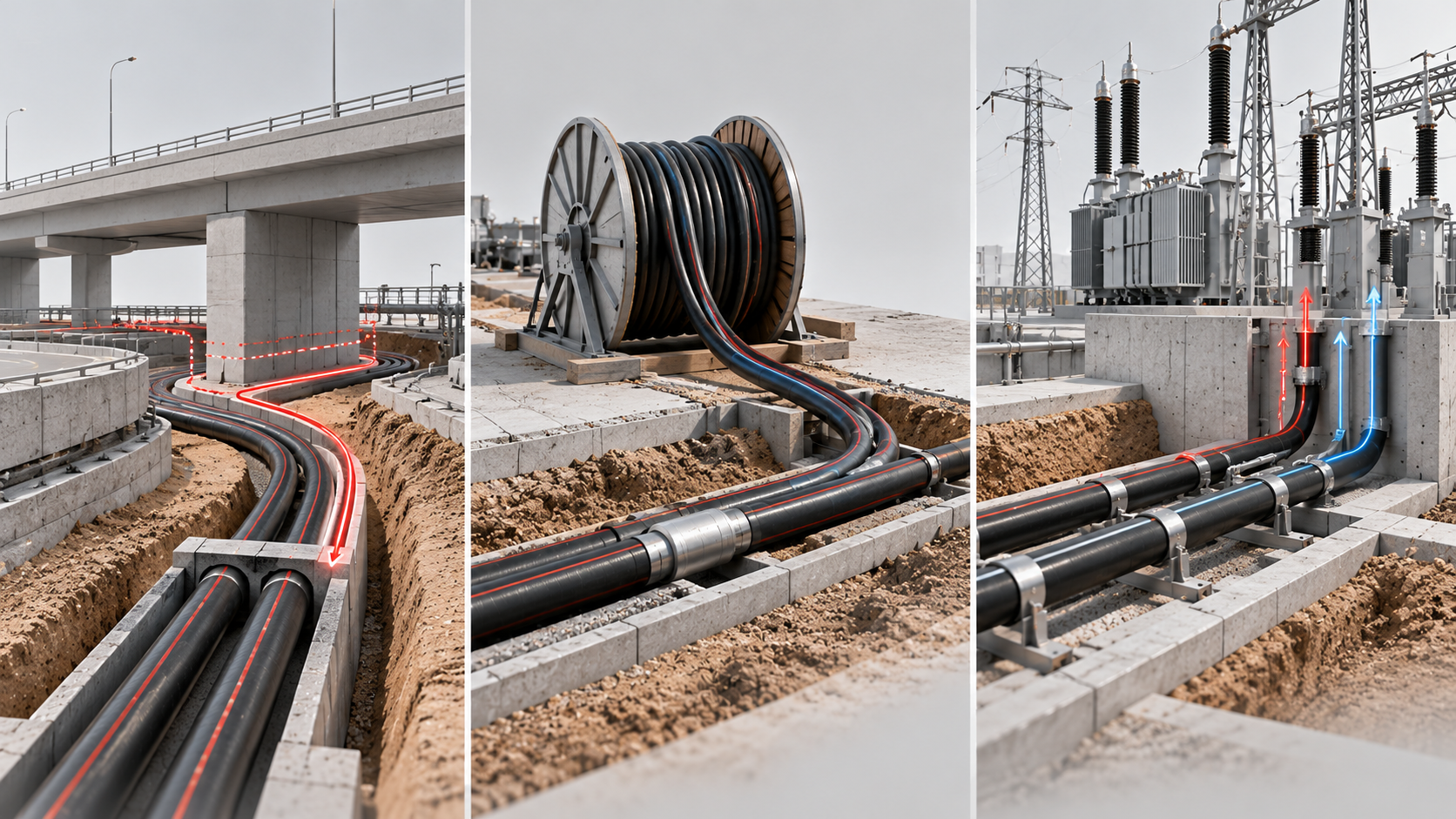
In real EPC projects, factors such as civil constraints, cable drum length limitations, and grid tie-in requirements often make it impractical to implement textbook bonding arrangements exactly as designed. Here are three practical design challenges and their solutions:
Challenge 1: Shifting Joint Bays Around Civil Obstacles (697 m, 380 kV Route)
On a 697 m, 380 kV direct-buried route (1000 mm² cable, 800 mm phase spacing, 1.7 m depth, 1.2 K·m/W backfill), sectionalized cross-bonding achieves 872.9 A (exceeding the 580 A requirement) and permits up to 591.94 m per minor section under fault induced voltage (16,049 V/km). While an ideal split yields 232 m + 232 m + 233 m, a site clash with a terminal compound at Joint Bay 2 forced an 8 m shift resulting in minor sections of 236 m, 236 m, and 225 m. Because all three sections remain well under the 591.94 m limit with minimal length imbalance, the adjusted layout operates safely within circulating current limits.
Challenge 2: When Drum Length Caps Your Cross-Bonding Section (1,780 m Route)
Consider a 1,780 m route where induced voltage calculations allow up to 600 m per minor section for cross-bonding and 300 m (with 1 GCC) for single-point bonding, but the maximum available drum length is 560 m:
· Why Standard 3-Section Cross-Bonding Fails:
Dividing 1,780 m / 3 requires 593.33 m per minor section. While 593.33 m < 600 m passes the electrical check, it exceeds the 560 m maximum drum length.
· Why 6-Section Cross-Bonding Is Costly:
Splitting the route into six minor sections (~296.7 m each) works technically but doubles the number of drums, joints, and link boxes, increasing cost and installation time.
· The Mixed Bonding Solution:
· Configure three cross-bonded minor sections at 550 m each (Drum length − 10 m margin = 550 m < 600 m), covering 1,650 m. Then terminate the remaining 130 m (1,780 m − 1,650 m) using Single-Point Bonding with 1 GCC (130 m < 300 m allowable limit).
The mixed bonding arrangement maximizes the use of cross-bonding over most of the route while complying with the 560 m drum-length limitation, thereby minimizing induced sheath voltages and losses. It also reduces the number of cable joints, link boxes, and accessories compared to a full 6-section cross-bonding scheme, resulting in lower installation cost and shorter construction time.
Challenge 3: Looping an Existing Cross-Bonded Circuit into a New Substation
An existing 5,613 m sectionalized cross-bonded circuit between Substation A and Substation B (with 450 m minor sections in its second major group) must be cut 111 m past Joint Bay 5 (JB-5) and diverted 538 m into a new Substation C (where cross-bonding Induced voltage allows 550 m, single-point Induced voltage allows 300 m, and max drum length is 560 m):
· The Trap: Splicing the 538 m extension directly onto the 111 m cut point creates a 649 m sixth section (111 m + 538 m) which is 44.22% longer than the 450 m adjacent sections and violates both the 550 m induced-voltage limit and the 560 m drum limit.
· The Mixed Bonding Fix: Install a straight joint at the cut point and pull 339 m of new cable to New JB-6 so Section 6 + Section 6A equals 450 m (111 m + 339 m), completing the 3 × 450 m cross-bonded major section with zero imbalance. The remaining 199 m (538 m − 339 m) into Substation C is then completed as Section 7 using Single-Point Bonding (199 m < 300 m limit).
4. Three Common Link Box and Grounding Mistakes to Catch Before Commissioning
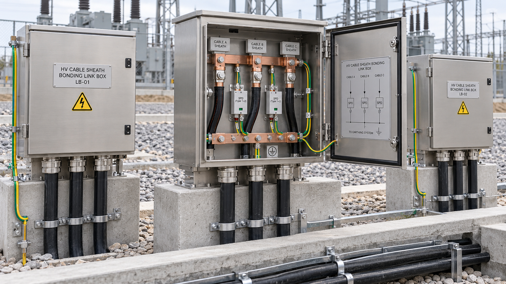
Even a rigorous bonding calculation can be undermined during detailed drafting or field termination. Watch for these three frequent site errors:
· Reversing Inner and Outer Coaxial Cores in Link Boxes:
Coaxial bonding cables bring the sheaths from both sides of an isolated joint into the cross-bonding link box. Swapping the inner and outer cores or misaligning clockwise (RYB → BRY → YBR) vs. anti-clockwise (RBY → YRB → BYR) transposition destroys the 120° phasor cancellation and induces high circulating currents.
· Specifying a 3-Way Instead of a 6-Way SVL Link Box at Mid-Point Joints:
In a mid-point bonding scheme where two 300 m sections meet at an isolated middle joint (with both ends earthed at the terminations), using a 3-way SVL link box shorts the left and right isolated sheaths together. A 6-way link box with SVLs is required so all six sheath leads are isolated independently.
· Installing Redundant Parallel GCCs Inside a Shared Substation Earth Mesh:
On short single-point bonded runs located entirely within a single substation (such as a 70 m run inside a substation gantry area), both cable ends are already connected to the same common substation earth mesh. Adding a parallel GCC provides no functional fault-return benefit and unnecessarily complicates the bonding arrangement.
Selecting and executing an EHV/HV bonding scheme requires looking beyond idealized three-section diagrams to account for drum transport limits, civil trench realities, and future grid cut-ins.
How does your engineering team handle routes where drum lengths or substation cut-ins prevent a clean three-section cross-bonding split do you lean toward mixed bonding or additional cross-bonding sections? Share your field experiences in the comments below or reach out to the Dar Engineering team to discuss your upcoming HV/EHV transmission projects.