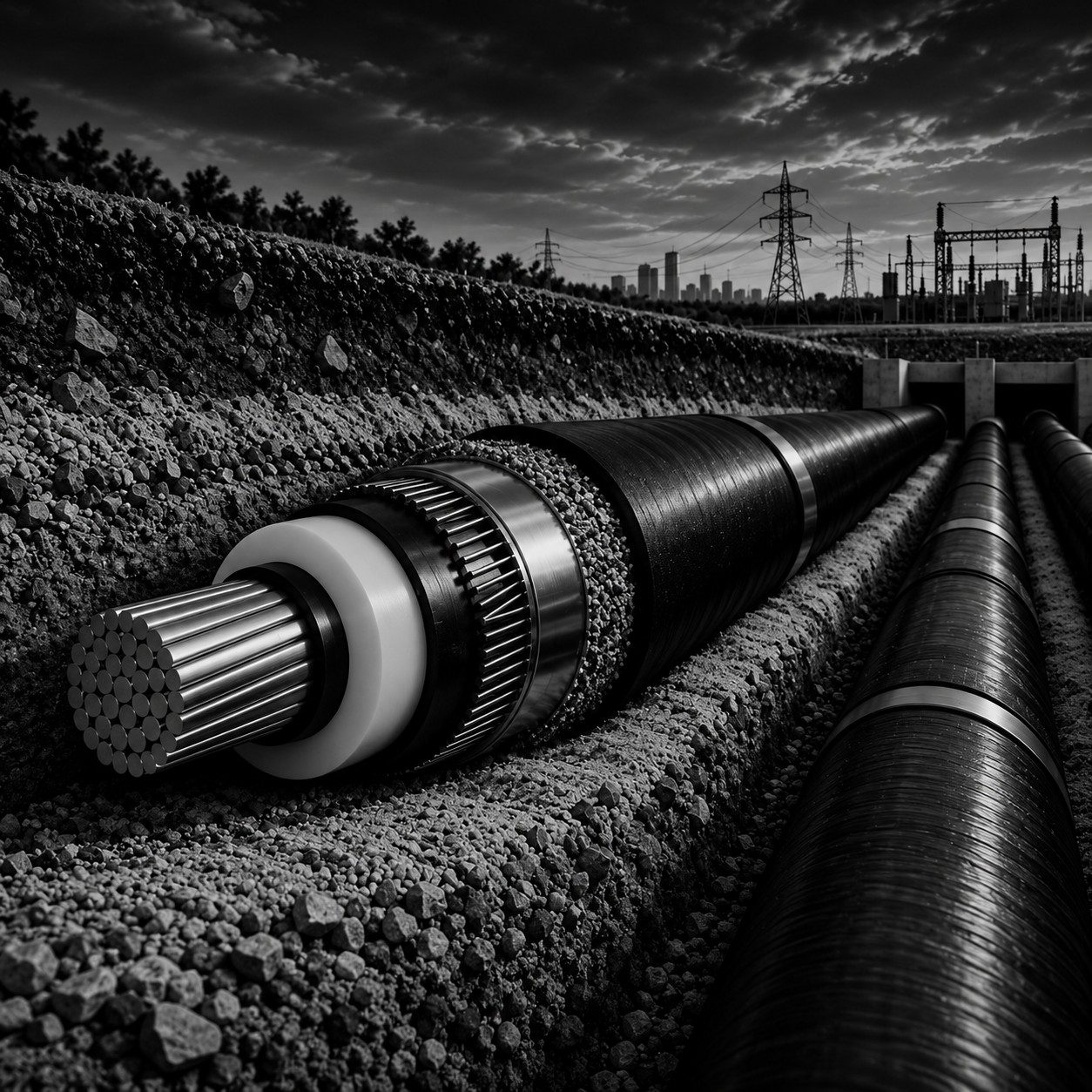
Five Critical Considerations for Safer and More Efficient HV/EHV Cable Systems
How thermal performance, fault withstand, sheath losses, bonding schemes, and installation conditions influence high-voltage cable design.
Reliable high-voltage (HV) and extra-high-voltage (EHV) power transmission depends on more than selecting the appropriate cable size. Every cable system must operate within its thermal limits, withstand electrical faults, maintain acceptable voltage levels, and meet the practical requirements of its installation environment.
These requirements are closely connected. A decision that improves one aspect of cable performance may introduce new considerations elsewhere in the design. For this reason, engineers need to evaluate cable systems as an integrated part of the wider power network.
Here are five critical considerations that support safer, more efficient, and reliable HV/EHV cable design.
1. Calculate Ampacity Under Actual Operating Conditions
Ampacity is the maximum continuous current a cable can carry while maintaining the conductor temperature within its permissible limit under specified installation conditions
When current flows through a cable conductor, electrical resistance generates heat. Additional losses occur in the cable insulation and metallic components. The cable reaches thermal equilibrium when the heat generated equals the heat dissipated into the surrounding environment.
However, the ability of a cable system to dissipate heat depends significantly on its installation conditions.
Ground temperature, soil thermal resistivity, backfill properties, burial depth, cable spacing, and the presence of nearby circuits can all influence underground cable ratings. Similarly, ambient temperature, ventilation, cable grouping, and solar exposure can affect installations in air or tunnels.
The expected load profile also plays an important role. IEC 60287 provides methods for calculating steady-state current ratings, while IEC 60853 provides methods for evaluating cyclic and emergency current ratings under time-dependent thermal conditions. IEC 60853-1 applies to cyclic ratings for cables up to and including 18/30 (36) kV, whereas IEC 60853-2 covers cyclic ratings for cables above 18/30 (36) kV and emergency ratings for cables of all voltage levels
Engineering takeaway: Cable ampacity should reflect the actual installation environment and expected operating conditions. A rating that is appropriate for one installation may not be suitable for another, even when the cable specifications are identical.
2. Verify Short-Circuit Thermal Withstand
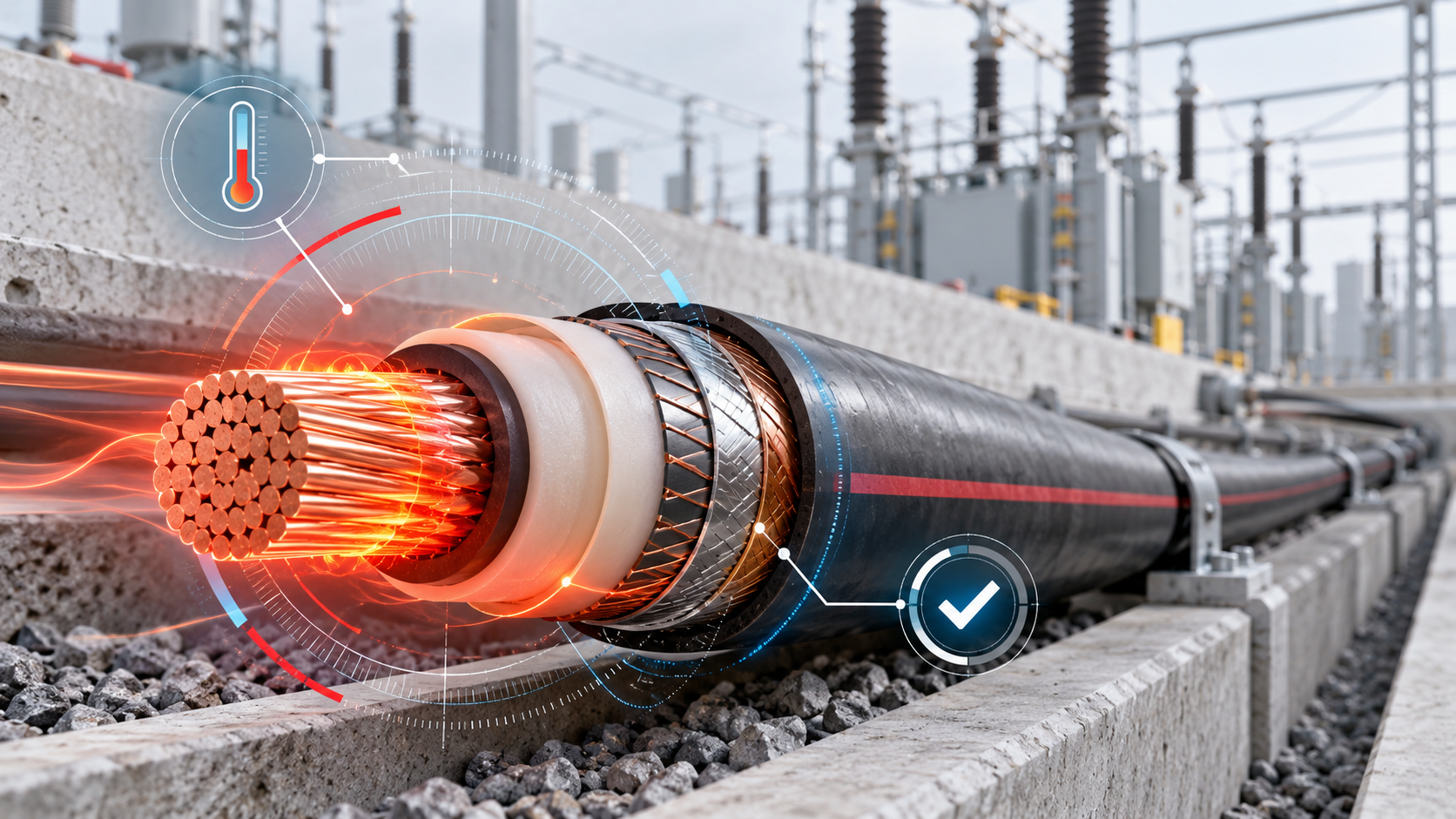
Cable systems must be designed to withstand both normal operating conditions and fault conditions. During a short circuit, high current can generate substantial heat within a very short period.
The assessment must consider the expected fault current, its duration, and the thermal withstand capability of the conductor and relevant metallic components, including the screen.
Adiabatic calculations assume that the heat generated during the fault remains within the component being assessed. Non-adiabatic calculations account for heat transferred to surrounding cable layers, where the applicable method and assumptions permit this consideration.
IEC 60949 provides the methodology for short-circuit thermal calculations and is commonly used to verify conductor and metallic component sizing under fault conditions.
This assessment is an essential complement to ampacity sizing. A cable that meets its continuous current-carrying requirement must still be checked against the specified short-circuit duty.
Engineering takeaway: Normal operating performance and fault withstand are two distinct design requirements. Both must be verified to establish whether the selected cable system is appropriate for its intended service.
3. Control Sheath Losses Through Appropriate Bonding
The metallic sheath of an HV/EHV cable plays an important role in the electrical and safety performance of the system. However, alternating current flowing in the conductor produces a varying magnetic field that can induce voltage in the sheath.
When the sheath forms a closed conductive loop, such as in a solidly bonded system, the induced voltage can drive circulating currents through the sheath. These circulating currents generate additional heat, increasing sheath losses and potentially reducing the cable’s available current-carrying capacity. Eddy-current losses can also occur, even in bonding arrangements designed to eliminate or minimize circulating currents
Bonding schemes help manage these effects. Common arrangements include solid bonding, single-point bonding, cross-bonding, and mixed bonding.
Each arrangement offers different performance characteristics. Solid bonding can simplify installation and keep sheath voltage low, but circulating-current losses may be significant. Single-point bonding interrupts the circulating-current path, but induced sheath voltage and fault-current return arrangements require careful assessment. Cross-bonding and mixed bonding may be appropriate for other route configurations and design requirements.
The objective is not simply to select the arrangement with the lowest losses. The chosen bonding scheme must achieve the optimum balance between ampacity, induced-voltage control, fault-current performance, personnel safety, constructability, and overall project cost
Engineering takeaway: Bonding selection is a fundamental design decision that directly affects cable losses, ampacity, induced sheath voltages, and system safety. The appropriate scheme should be selected based on route length, grounding topology, fault-current requirements, and practical installation constraints.
4. Manage Induced Voltage and Electrical Safety
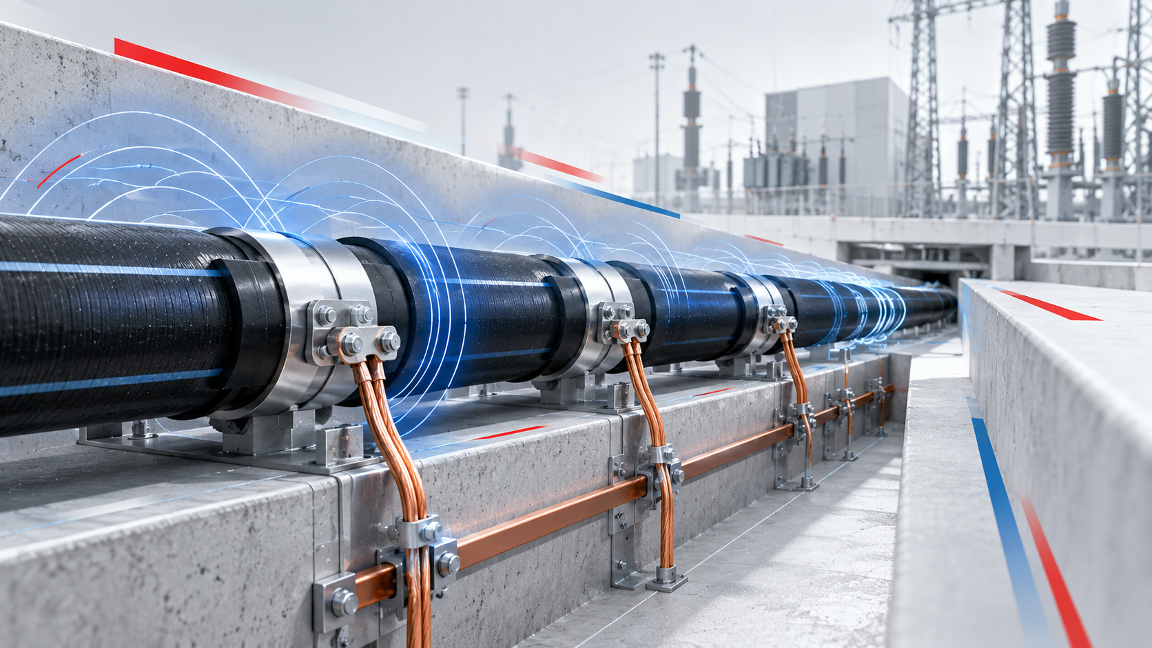
Induced sheath voltage is another critical consideration in cable system design. The voltage produced on the cable sheath under normal operating conditions may differ substantially from the voltage arising during a fault.
Engineers must assess both operating and fault conditions against the applicable project, utility, and international requirements. The evaluation should consider the cable route, bonding configuration, and the electrical characteristics of the installation.
The bonding arrangement must also provide an appropriate path for fault current. Depending on the bonding scheme, an earth continuity conductor (ECC) may be required to support the fault-current return path. Sheath voltage limiters (SVLs) may also be needed to help control sheath voltage under specified conditions.
These components must be designed in coordination with the overall earthing and protection system rather than considered independently.
Engineering takeaway: Reducing sheath losses is not enough. A suitable cable bonding scheme must also maintain induced sheath voltage within acceptable limits and provide an adequate fault-current return path, and ensure safe operation under both normal and fault conditions.
5. Integrate Installation and Route Constraints into the Design
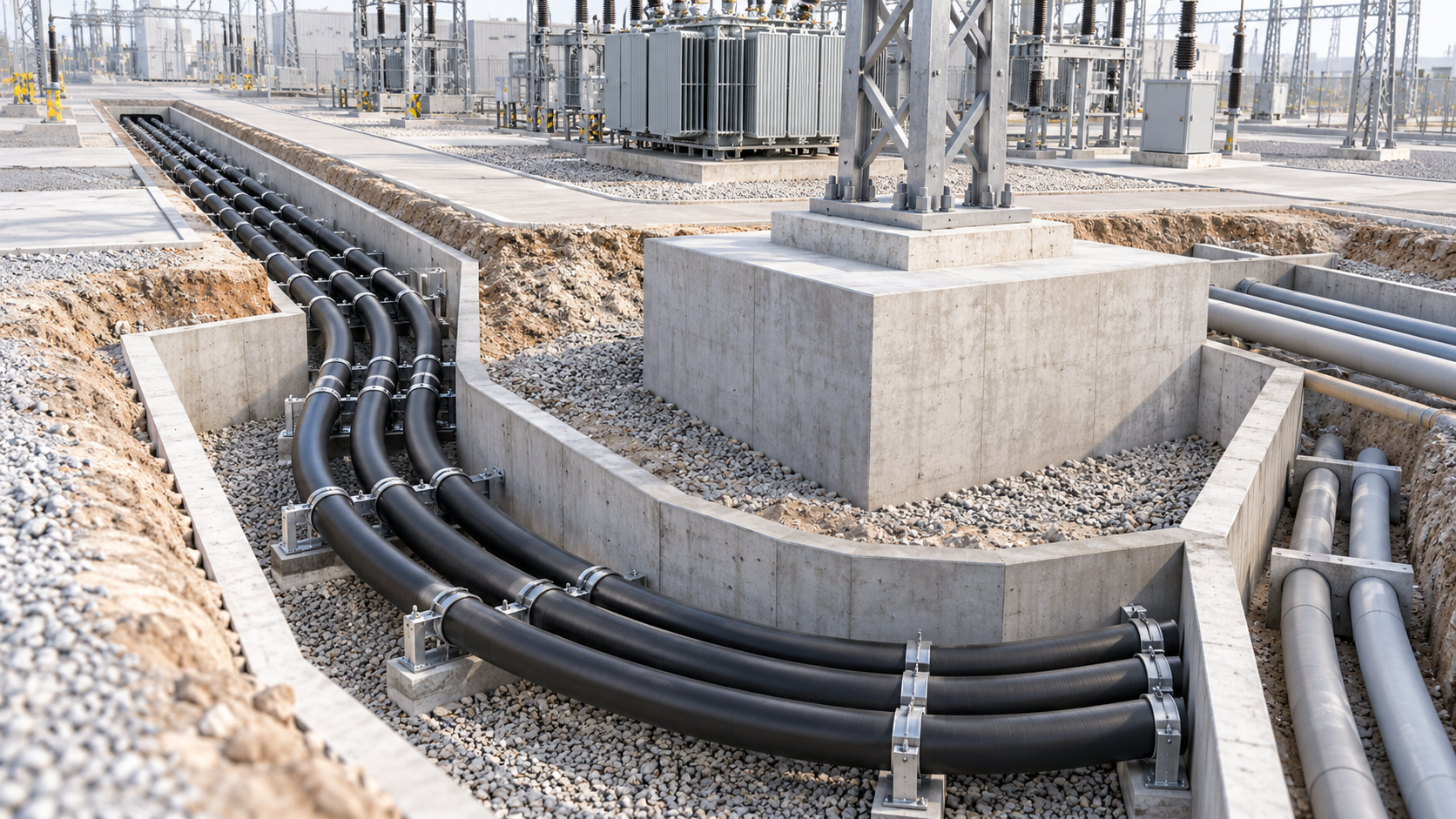
Cable calculations ultimately need to translate into a practical installation. Route conditions can influence both thermal performance and bonding-scheme selection.
For underground installations, factors such as burial depth, soil thermal resistivity, phase spacing, and nearby circuits must be considered in the relevant assessments. Route length, available cable drum lengths, joint-bay locations, and connections to existing circuits can introduce further constraints.
For example, a proposed cross-bonding arrangement may satisfy the induced-voltage requirements but prove impractical because the calculated section lengths exceed the available cable drum length. In such cases, engineers may need to assess alternative section lengths or a mixed bonding arrangement, provided the revised design satisfies all applicable electrical and installation requirements.
Changes to an existing route also require careful review. Adding a new connection or modifying a cable section can affect the original bonding arrangement and require the design to be reassessed.
Engineering takeaway: A technically sound design must satisfy electrical requirements while remaining practical to construct, install, and integrate into the wider network.
Design for Performance, Safety, and Reliability
Ampacity, short-circuit thermal withstand, sheath losses, induced voltage, and installation constraints are interconnected aspects of HV/EHV cable design. Evaluating them separately without checking their combined effect can result in an incomplete assessment.
A systematic engineering approach brings these considerations together, helping align cable performance with safety requirements, installation conditions, and operational needs.
The selected cable and bonding arrangement should therefore be evaluated as part of an integrated system rather than as individual components.
Which of these five considerations presents the greatest challenge in your HV/EHV cable projects?
At DAR Engineering, we recognize the importance of combining detailed technical analysis with practical engineering judgment to support safe, efficient, and reliable infrastructure.
Related Post

What is the Difference Between a Project Schedule and a Project Plan?
READ MORE
MEP Design for VIP Stadium Hospitality, Navigating FIFA Standards and Saudi Codes
READ MORE
Unmovable Deadlines: The Executive Playbook for Fast-Track Mega-Project Delivery
READ MORE